
Making The Foundation
During my last trip to the lumber yard, I found the perfect piece of 12/4 walnut that had some nice curly figure to it and was long and wide enough to make the entire base frame and all four legs from a single piece of timber that fit into my car. Sometimes things just work out perfectly but then again sometimes everything that can go wrong will, so maybe it is all just a matter of chance. I’m already a little off course with this but my point is that there are good days and bad days in woodworking. This was a good day.
The Frame
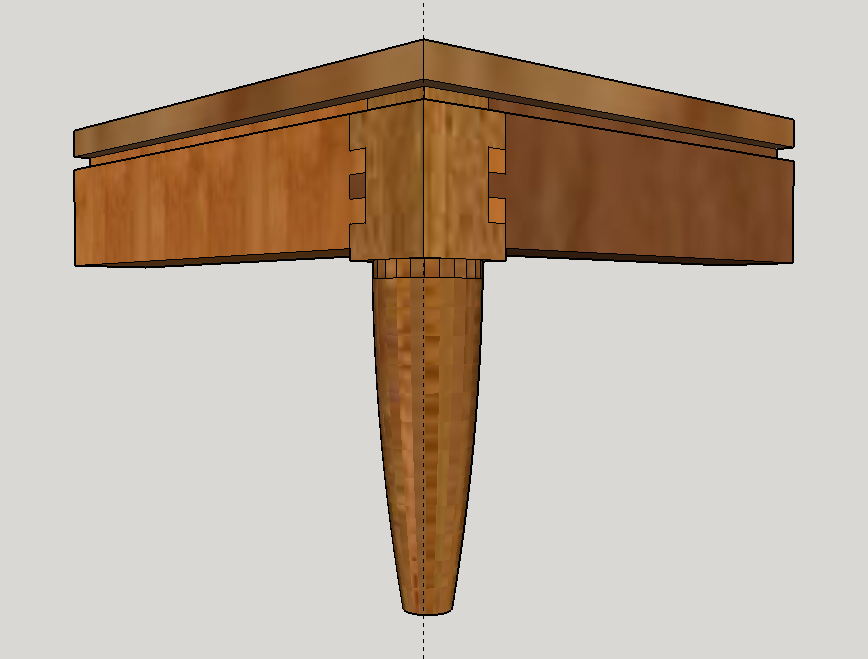
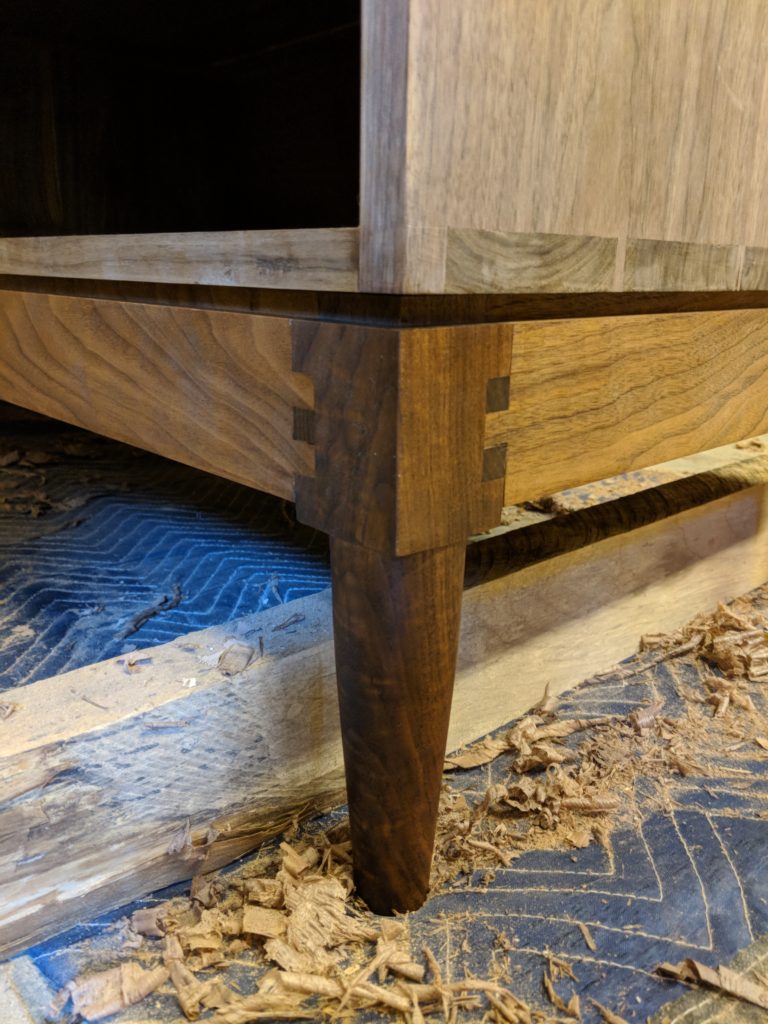
I planed the 12/4 down to its finished thickness and ripped it into boards that would make the four frame sides, four legs and a stretcher in the middle for some added support. As I mentioned in Part 1, it was important to me that the base frame and legs connection be strong enough to withstand any lateral forces applied to it without the possibility of weakening or worse, snapping off. The strongest joint I could think of was the rocking chair joint or, as I will call it, the Sam Maloof joint. My application was a little different than a rocking chair so I decided to first draw it in SketchUp to make sure it would look how I wanted. I consider AutoCAD or SketchUp one of the most important tools in a woodworker’s kit. If you don’t already have SketchUp, download it here for free. I’m afraid you’ll have to pay for AutoCAD.
SketchUp Model
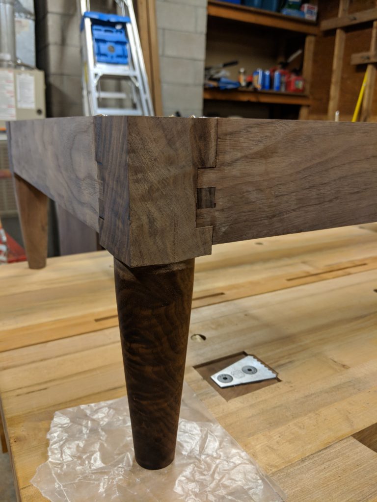
A strong joint needs lots of long grain surface area for the glue to make contact. The miter joint was out because it is mostly end grain. The finger joint matched the original design and had a lot of glue surface area but it needed some modification to work with the Maloof joint. Ultimately, I chose a modified bridle joint which was close to a finger joint but with just one tenon which was offset ever so precisely so as to create equally spaced fingers when the leg was installed.
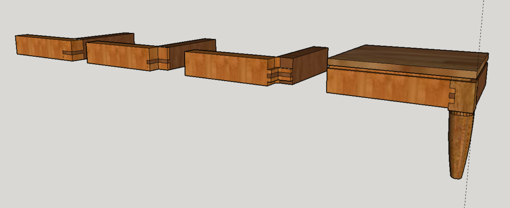
I won’t go into the exact process for cutting a Maloof joint. You can find that easily online but I did want to show how the four completed stages of creating the joint should look in the image above. Having this was very helpful because I could use the dimensions at every stage of the model to set my marking lines and router bit depths on the actual piece.
The Legs
About this time, I found myself at a dead stop until I could access a lathe to turn the legs. Unfortunately, I had to put the project on hold for a bit while I saved up enough money to buy a JET mini lathe from Woodcraft. This was my first time wood turning so I used the down time to do research on YouTube. Lately it seems YouTube has become my go to resource for self service education whether it be woodworking techniques for my hobby or software tips for my job.
Wood Turning
Here is a tip to anyone thinking about getting into wood turning; buy good turning tools. I started with some discount gouges and got so many catches that I almost gave up. After talking to my local Woodcraft guy, he convinced me that because I only plan to turn occasionally, and not make it my primary woodworking discipline, that I should consider carbide insert tools. This made a huge difference and they never need sharpening!
The first leg came out okay. The next few were a bit better and the last couple were great. At the end of the day, I made seven legs and chose the best four. Maybe I will use the remaining three for another project someday. I sanded the legs up to 320 grit on the lathe. This was the only time sandpaper ever touched this project.
Assembly
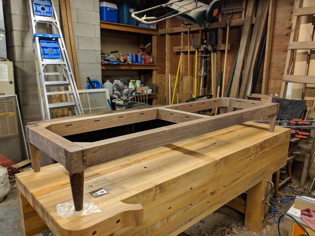
Before gluing up anything, I had to use the router to cut slots in all four base sides and the middle stretcher to receive the buttons. More on that later. I also had to cut tongue and groove joints to receive the middle stretcher that would provide extra support to the base and also finish all the surfaces with the hand plane.
Now it was time to cut the joinery. The modified bridle joint was cut using the tenoning jig on the table saw which was fine for the sides but a little precarious for the front and back because they were so long it required a bit of a balancing act. This probably could have been done more safety with a hand saw. I applied glue to the cheeks and clamped the assembly up overnight.
In the morning, I cut the notch with a Japanese ryoba saw and routed the shoulders for the Maloof joint with a rabbeting bit. I said I wouldn’t go into this process in detail so here is a good video if you are interested.
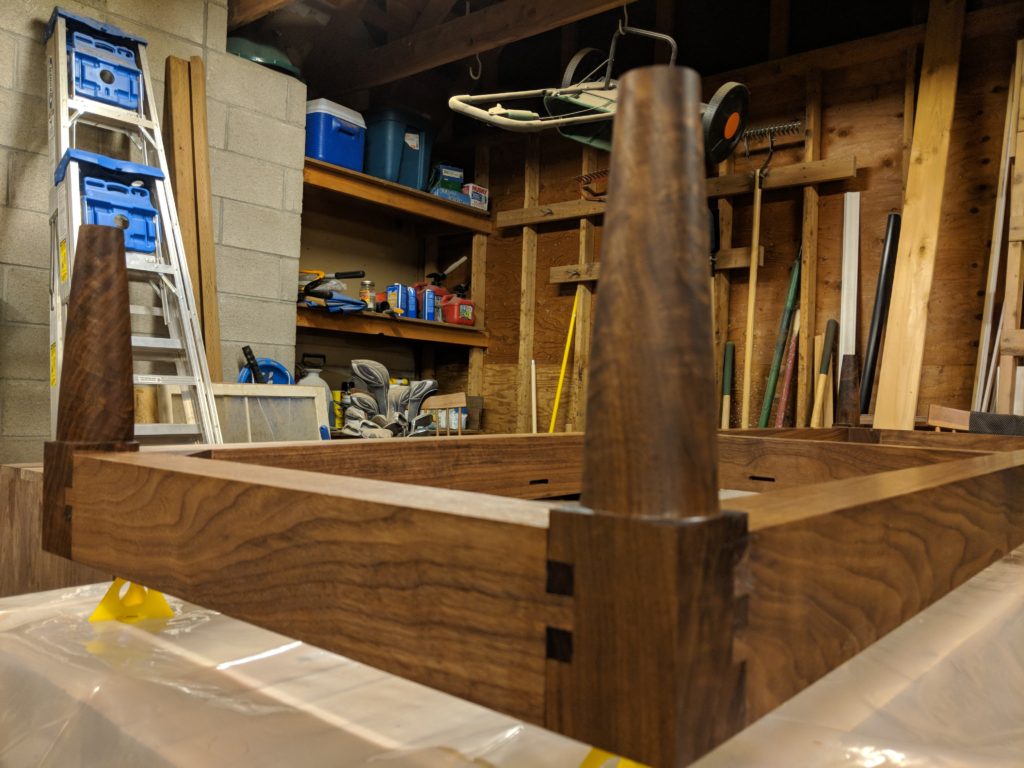
I decided at this point that the corners needed more strength since the notch removed much of the supporting material in making the Maloof joint. I cut four 45 degree corner gussets out of walnut and glued them into the inside corners. This not only provided more rigidity to the frame but also created a perpendicular clamping surface for the legs.
I cut the remaining joinery for the legs with a miter gauge on the table saw; sneaking up bit by bit to get a tight fit. A round-over bit on the router table finished off the joint and I applied glue to all surfaces, clamped them up and let them dry overnight.
The legs were left proud of the surface of the base by just a hair so they could be planed flush. Lastly, I applied two coats of the Danish oil to everything which really made the grain and joinery details pop.
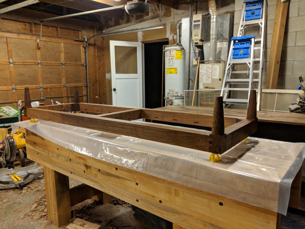
Attachment
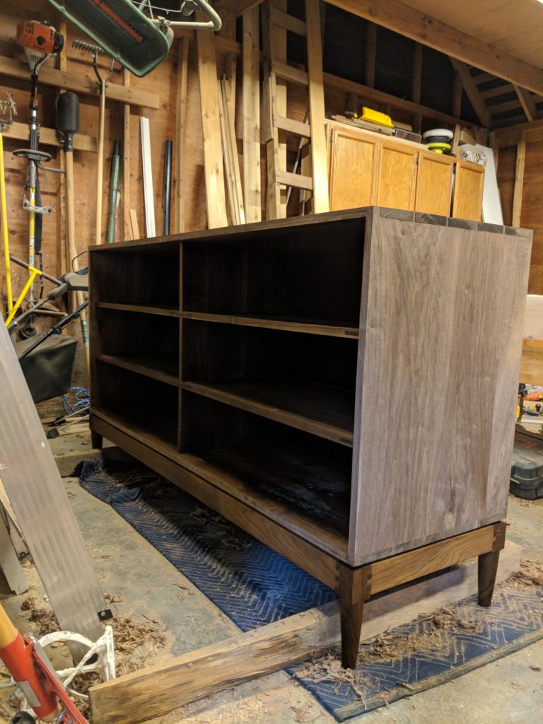
The time had come to put the base and the case together. This felt a bit like when auto manufacturers “marry” the chassis to the body and it finally becomes a car. Kinda like that.
Reveal
Here is a trick I learned during my time in construction management working alongside architects. When you have two components that need to be co-planar but are manufactured separately (such as a metal panel wall or acoustical ceiling panels) they will never line up perfectly if they are butted-up against one another. What’s worse is that the error will be accentuated because the human eye will perceive the shadow line created by the gap to be worse than it actually is. The trick is to intentionally create a gap (i.e. reveal) between the components that is wide enough that the human eye cannot perceive that they don’t line up perfectly. This tricks the eye into signaling to the brain that they in fact do line up perfectly since the brain naturally wants to conserve processing power by making assumptions about visual signals that are just noise. What the eyes see, the mind believes.
I used the same rabbeting bit I used for the Maloof joint to cut a 3/8″ reveal around the top of the base. This created the visual separation that concealed that fact that the base and case did not line up perfectly along their face planes (they were very close though) and also gave the visual impression that these were two distinct components; a top and a bottom. It also cut the height of the leg corners so that the Maloof joints now had equally sized shoulders, top and bottom.
Buttons
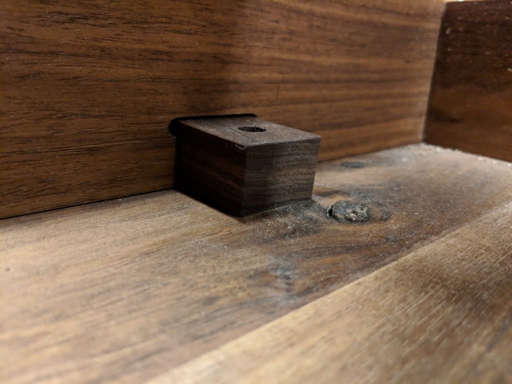
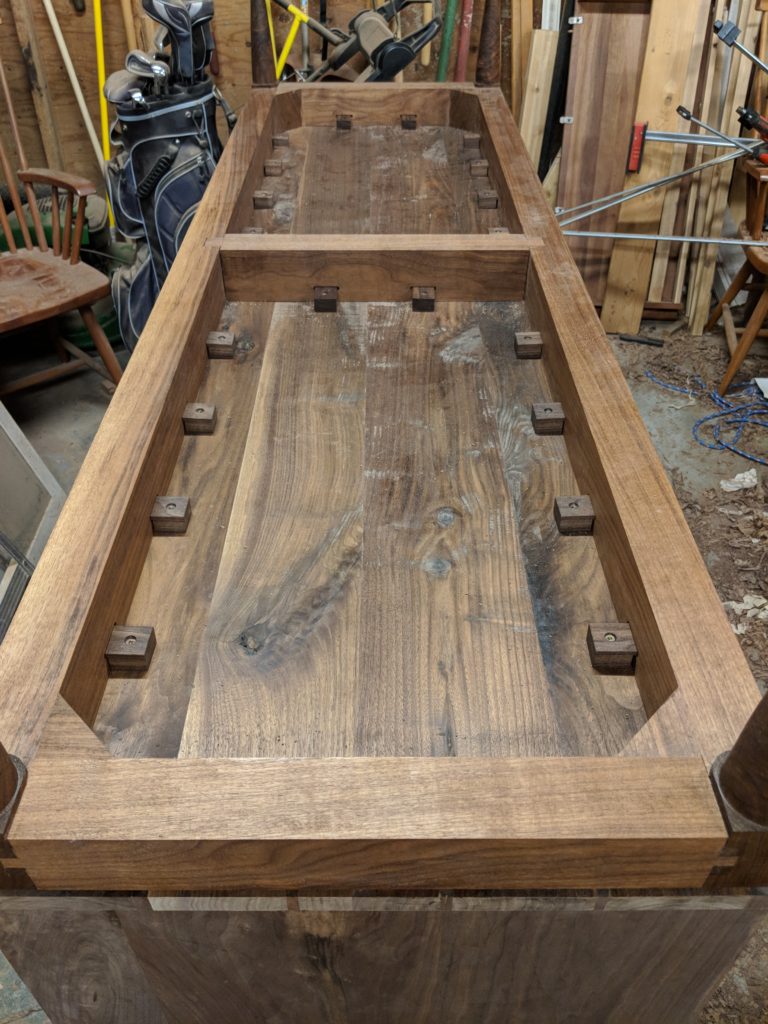
Wood moves perpendicular to the grain direction and the bottom of the case has a lot of width to move so I had to attach the base in a such a way that would allow for this. The answer was obvious; buttons.
Cutting all 24 buttons individually would be too time consuming so I needed to take a more production oriented approach. I used a dado stack in the table saw to first crosscut multiple deep grooves in a single board to make the tongues. Then I ripped the board to the width of the button which resulted in multiple strips of buttons all connected end to end. Then I cut them apart. There are two very important things to note here. First is that the grain of the button must run length wise or from front to back. Wood has the most strength perpendicular to the grain and if the grain ran width wise or side to side, the tongue could easily snap off when tightened down. Second is that the height to the underside of the tongue must be a bit less than the height to the bottom of the slot that the tongue will fit into. This is because there must be a small gap between the button and the surface it screws into so that it can pull the case and base together. If the button bottomed out flat, it wouldn’t actually hold anything in place.
I countersunk a screw hole in the center of each button making sure not to go too deep so that the screw might pop out the other side. Then I finished all the buttons with oil and aligned the base to the case in exactly the right spot. I drilled pilot holes and screwed each button down by hand so that I didn’t strip anything. My neighbor Bill was kind enough to come by and help me flip the whole assembly over and voila! We had a car.
Up next : Part 4 – The Drawers will continue the story by walking through the making of six boxes that are smaller versions of the case and mounting the drawer fronts that include an integral pull detail.